A 100% solar application
Since the start of getting going with esp8266 boards in late 2015 I’ve had in the back of my mind the idea of how nice it would be to develop a little device that is free of all ties to a regular plug-in-the-wall power supply. With no plug in supply, we’re talking about battery power and if the goal of this project is complete independence then we’re talking rechargeable battery power. If this dream was a reality then the idea is that the device could go anywhere and be positioned anywhere, within WiFi range.
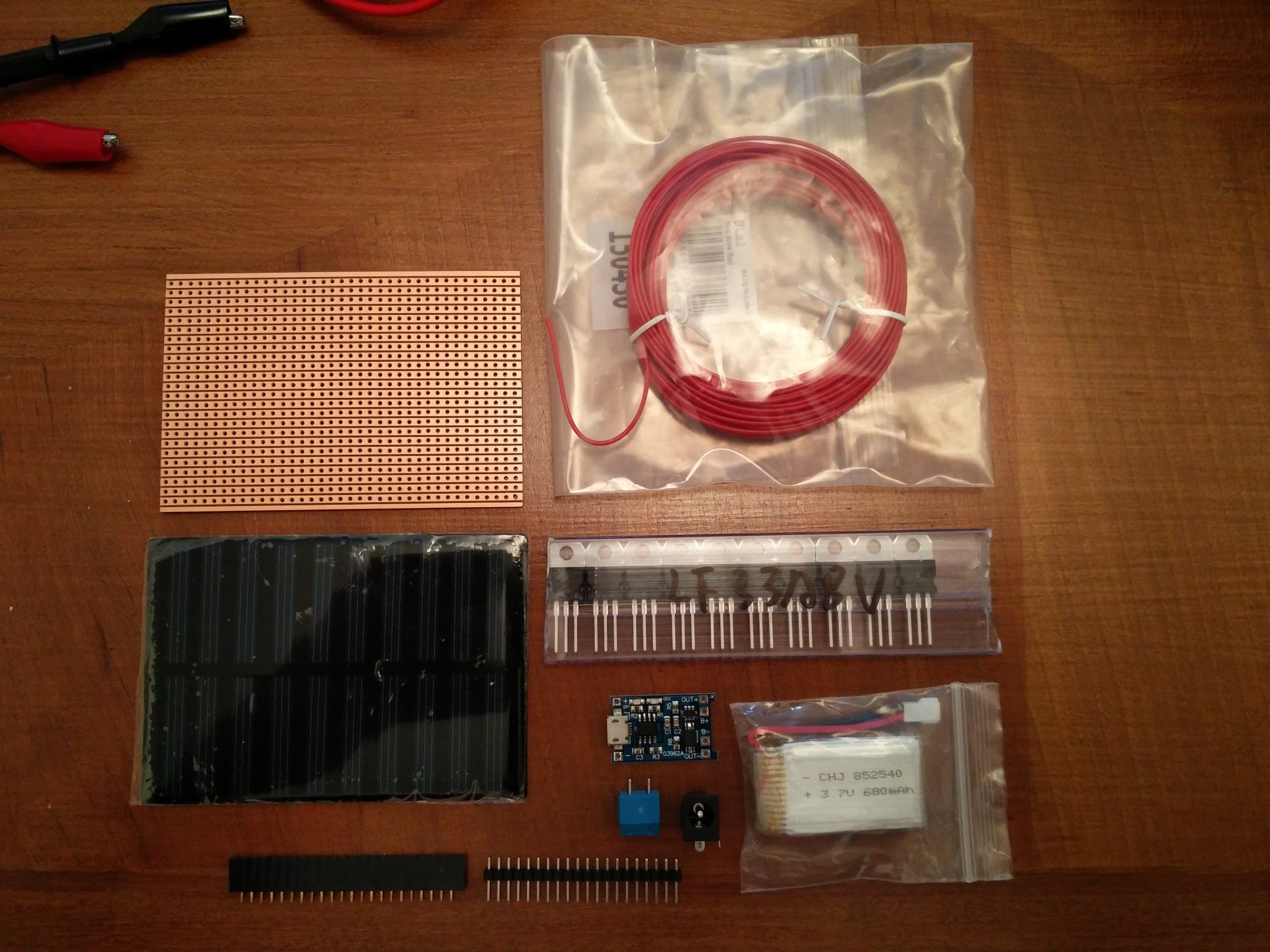
I kept this idea bubbling in the background whilst building out other more general features of my custom web based ESP firmware and a few months ago I started gathering bits and pieces from aliexpress and eBay to form the basis of a prototyped custom rechargeable battery solar power supply. The parts list I gathered together was:
- Stripboard for prototyping e.g. http://www.ebay.co.uk/itm/Strip-Board-Printed-Circuit-PCB-Vero-Prototyping-Track-Packs-of-5-/261199157440
- Male & Female Pin Headers e.g. http://www.aliexpress.com/item/1-lot-10pcs-1x40-Pin-2-54mm-Single-Row-Female-10pcs-1x40-Male-Pin-Header-connector/32270625162.html
- LF33ABV LDO power regulator(s). I opted for this LDO regulator for it’s low quiescent current characteristics e.g. http://www.aliexpress.com/item/Free-shipping-4pcs-LF33ABV-IC-REG-LDO-3-3V-0-5A-TO220AB-Voltage-Regulators-chip/32697234456.html
- 2.1mmx5.5mm DC Female Socket Power Jack(s) e.g. http://www.ebay.co.uk/itm/231933446157
- Lithium battery charging circuit board(s) with overcharge and overcurrent protection e.g. http://www.aliexpress.com/item/Free-Shipping-5V-1A-Micro-USB-18650-Lithium-Battery-Charging-Board-Charger-Module-Protection-Dual/32453058256.html
- A rechargeable battery of some sort. This is the actual Li-Po type I first went for because it was cheap albeit slightly underpowered: http://www.ebay.co.uk/itm/281909930938. After some experimentation I later found this was the wrong choice of battery because these types of RC batteries are built to drain all the way down and actually don’t work properly with the lithium charging board above. I eventually mutilated an old laptop battery and salvaged a bunch of 18650 2200mAh cells still in decent shape.
- Solar panel(s). Again this is the actual panel I went for because it was super cheap: http://www.ebay.co.uk/itm/282033457663. Again after experimentation I found this panel to be the wrong choice because it was woefully under-specced for my needs and in the end I went for one of these instead - still 5v but with the ability to deliver a 500mA charge which is sufficient for charging a 18650 cell: http://www.ebay.co.uk/itm/161347478808
- Wire. Lightweight thin insulated stuff for prototyping that looks like this: http://www.ebay.co.uk/itm/330714933676
- Capacitors for smoothing/filtering and power spike/drop handling. These are the usual suspects in any esp8266 rig i.e. a 0.1uF ceramic filtering cap and something like 100uF electrolytic power spike caps. Get these from wherever e.g. http://www.ebay.co.uk/itm/252459102360 and http://www.ebay.co.uk/itm/291263960300
- PCB connector block(s) e.g. http://www.ebay.co.uk/itm/251974851948
- An ESP8266 board of some sort - I usually go for ESP12F boards e.g. http://www.aliexpress.com/item/Esp8266-WiFi-series-of-model-ESP-12-ESP-12F-esp12F-esp12-authenticity-guaranteed/32468324806.html
- The bog standard ESP white breakout board found everywhere e.g. http://www.aliexpress.com/item/10Pcs-Set-ESP8266-WiFi-Modules-Breakout-Transfer-Board-Adapter-Plate-For-ESP-07-ESP-08-ESP/32655534675.html
- Solder + soldering iron + good eye sight and lots of patience :)
Parts in pieces:
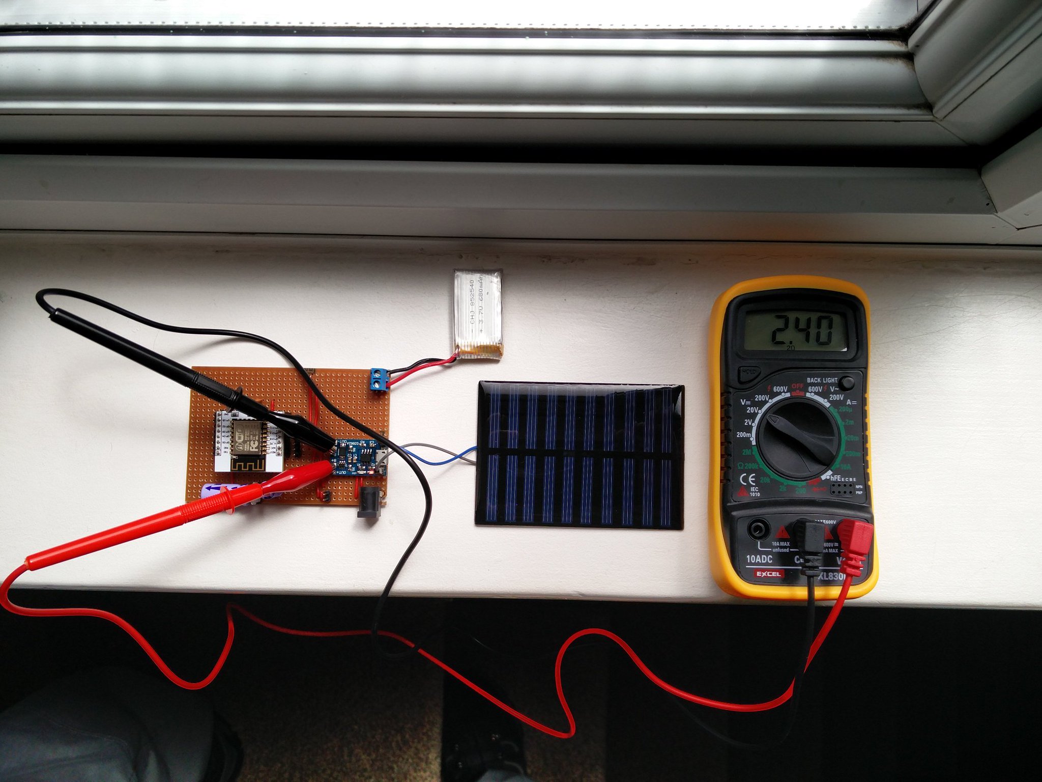
Parts assembled:
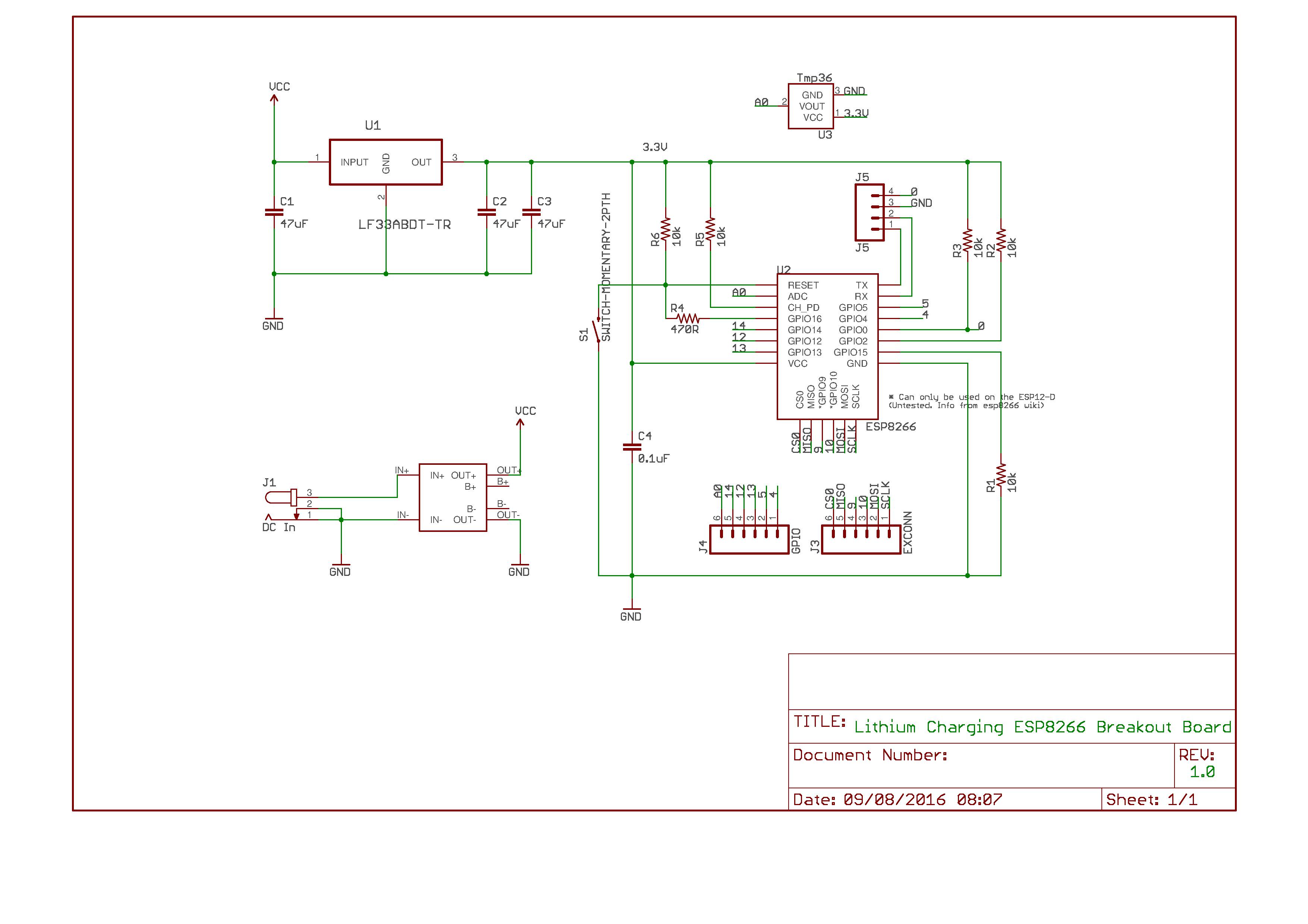
The circuit:
The good (options)
The 18650 lithium battery charger I’ve called out above is a super cheap really flexible board. I’ve no clue how on earth anyone is making any money selling these at £0.28 a piece (price correct at 21/07/16) but as a buyer / tinkerer, at this price you can’t go wrong. As long as you have some method to supply 5v to the left side of this board and you have a rechargeable battery connected to the right side, you’re good to shove that output voltage through an LDO regulator to get to the 3.3v you need for an esp8266 board. So in this case we’re connecting a little solar panel onto the pins on the left side of this charger board for regular charging purposes, but there’s also a little micro USB connector on the 18650 board which means if you want, you can charge your battery using any old samsung phone charger you have lying around. For convenience I also decided to add a female DC jack socket to my prototype rig so the battery could also be charged using a 5v wall mains charger with a jack type socket.
The bad
After spending one Saturday a few weeks ago building this prototyping rig, I charged my little mediocre 670mAh battery to the max using an old phone charger and let an loose esp8266 on it running my web based firmware with no charger present just to see how long the battery would last on a full charge. To be completely honest I’m not sure how long it ran for but it was somewhere in the region of hours rather than days or months ;)
Undeterred the next day I charged the little battery to the max again and performed the same test with the solar panel in place and left the device running on a semi-sunny / mostly cloudy window ledge (aka British summer time) :
I left it running there, went to work and when I checked it later in the day it had ran out of juice again.
At this point I ran some estimated numbers through http://oregonembedded.com/batterycalc.htm for the dismal 670mAh RC battery which indicated that at non stop (no sleep) operation I could expect something like 0.5 days battery life time if performing a WiFi broadcast every 15 seconds.
After a couple more days playing around, I clearly had a couple of problems:
- My battery and solar panel choices were rubbish and that needed to be fixed by simply choosing the right parts for the job (mentioned above in the parts list).
- Even with the right choice of battery and solar panel, the available battery power charge would not last forever even in the best mediocre british summer, so whilst waiting for replacement parts to arrive I decided that it was time to introduce power management features into my web based firmware.
Power management features shopping list:
I came up with these ‘must have’ features for this area:
- The big power management on/off switch
- Automated deep sleep with confgurable sleep interval including sleep after single cycle (sleep as soon as physically possible)
- A reduced feature set when running in single cycle mode e.g. don’t start web server / socket server / MQTT when woken and operating in this mode
- On wake up, stay awake time for a configurable length of time
- Logging of wake / sleep events to ThingSpeak and HTTP
- Detection of hard boot / manual power cycle to enable automated deep sleep to be delayed for a short while. This enables the web interface to be usable for configuration changes
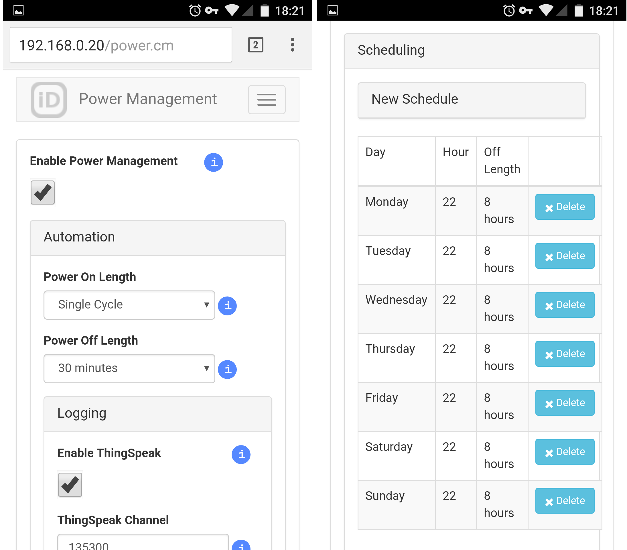
- A scheduled deep sleep feature to work in combination with NTP supplied time. This would enable long sleep periods at specific times of the day on specific days of the week e.g. sleep at 22:00 on Tuesday for 8 hours.
Power management screenshots
So that works..
Ok let’s be realistic, it did work after a couple of days hacking, head scratching and debugging.
I left the device running for the next 4 days on an initially fully charged 18650 cell measuring 4.06v, no solar panel attached on a 30 minute wake / instant sleep cycle with 8hr overnight sleep schedule enabled. After 4 days I measured battery volt drop down to 4.02v. Running the numbers through http://oregonembedded.com/batterycalc.htm again with this new mode of operation indicated an estimated 120 days battery lifetime. With solar panel charging this interval would be extended.
So what’s next? I’m currently in the middle of design and build of a PCB version of this lithium charging ESP8266 breakout board swapping all the chunky prototype components for SMD components.
This is my first attempt at using Eagle CAD and PCB design and I’m using OSH Park as my PCB print shop. Admittedly my first attempt has been a bit of a disaster all of my own doing but it’s looking like the end result is going to be a 2 layer board somewhere around 45x37mm. When it’s built and working I’ll write it up.


Comments